The historical arcT2 · external source
Medtronic has been here before. The first nuclear-powered pacemaker was implanted in 1970 (Doyle, "Rise and Fall of the Nuclear Pacemaker"), and in the early 1970s Medtronic teamed with the French company Alcatel on a plutonium-238-powered pacemaker whose decay heat drove a thermoelectric stack (Medical Design & Outsourcing). Hundreds were implanted (a Newark hospital alone tracked 155 units; one French series counted 325 patients — Doyle), and the longevity was astonishing: one 1973 recipient's device was still pacing 34 years later, where a chemical battery would have demanded repeated replacement surgeries (ORAU Museum of Radiation, accessed 2026-07-22; details re-attributed to their specific sources after adversarial QA). The approach faded — regulation, plutonium logistics, and the lithium-iodine battery won — but the dream (a power source that outlives the patient's need) never died.
The problemT1 · from the patentUS10096393B2
Modern betavoltaics skip the heat step: beta particles from a decaying isotope strike a semiconductor junction and generate electron-hole pairs directly, like a solar cell lit by radiation instead of sunlight. The catch — per the patent's description of what its 3D architecture improves (the background itself is a neutral recital of prior converters): flat junctions offer limited collection surface, and charge carriers can recombine before they're collected.
The principleT1 · from the patentUS10096393B2
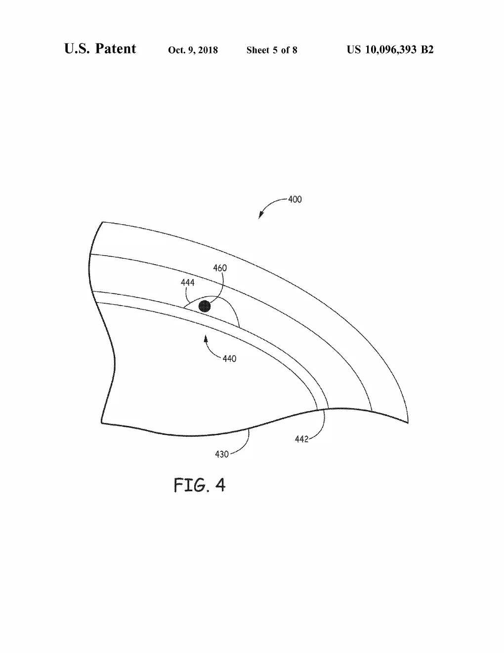
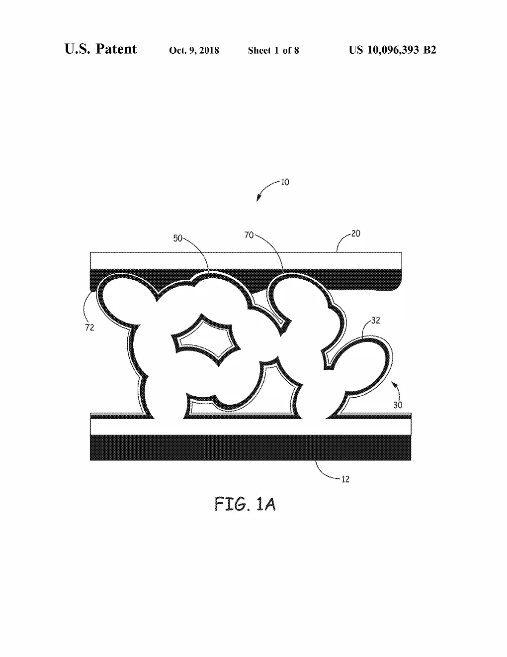
Make the collector three-dimensional. Claim 1 builds the converter around a 3D current collector — nanorods, nanotubes, metal foam — coated with a charge-carrier separator (quantum dots are among the named embodiments) and a hole-conductor layer, with the radiation source placed so particles strike the separator. The nanostructure can "maximize a surface area … for any given volume" (verbatim, ellipsis ours), so far more of each particle's energy finds a junction before recombining. Named fuel candidates run from tritium to Ni-63 to Sr-90. A sibling line (US10818811) takes a different path: isotope → phosphor light → photovoltaic — a glow-in-the-dark battery, hermetically sealed by the same packaging craft as everything else in the corpus.
Plain-English registerT3 · interpretationconfidence: high
A flat solar panel wastes a floodlight shining from every direction. Crumple the panel into a sponge and hang the light inside it, and almost every ray lands on a working surface. That's the 3D collector — a sponge for radiation.
Honest statusT3 · interpretationconfidence: medium
Five grants (2018–2024) and sustained follow-on filings show real Medtronic investment, but no public source indicates a shipped nuclear-powered Medtronic product today — we don't claim one. What the record supports: this is forward-looking R&D reconnecting the company to its own atomic history, aimed at the same prize the 1970 device chased — implants that never need a battery change.
Set-piece note (for Presentation)T3 · interpretation
Split-screen: 1970 archive-styled Pu-238 pacemaker (thermal glow) fades into the modern converter — camera inside the nanostructure sponge, beta particles streaking in, each strike lighting a junction like rain on water. History → future in one dissolve. (Patent figures are public domain; period imagery needs sourcing/licensing care.)