The Forge · Heat I · Hermetic Packaging & Feedthroughs · 1993-1996

1993: The First Housing

US 5,535,097

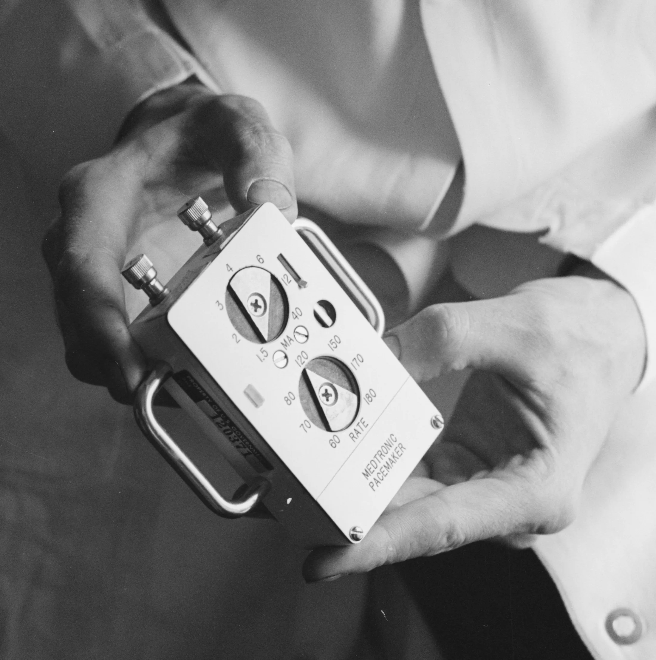
Hands on a boxy external MEDTRONIC PACEMAKER, 1961 — the machine this chapter teaches to live inside the chest. — Warren K. Leffler, U.S. News & World Report Magazine Photograph Collection, Library of Congress — public domain, via Wikimedia Commons

The origin pointT1 · from the patentUS5535097A

Filed November 23, 1993 — the earliest patent in the corpus, with David A. Ruben first on the inventor list. The subject could not be more foundational: the pacemaker's body itself — the hermetic housing, and the connector module that joins it to the lead running into the heart.

The problemT1 · from the patentUS5535097A

The background section is a compact history of pacemaker construction: discrete components potted in epoxy; then sealed metal cans. By the early '90s the standard was a "clam shell" — two halves butt-welded around the electronics, requiring weld-ring protection and separate plastic cups to position components. Many parts, many steps, many chances for error.

The stepped shell — parts locate themselves battery · circuit · capacitor settle into machined steps battery hybrid circuit cap then the lid welds shut — one seam, hermetic for a decade
Set-piece · the parts locate themselves

The 1993 move, animated: battery, hybrid circuit, and capacitor drop into machined steps that position them without cups or guesswork — then a single laser seam welds the lid shut. Static view: the housing assembled and sealed.

The principleT1 · from the patentUS5535097A

Redesign the enclosure so the parts locate themselves. Claim 1: a first enclosure portion with a planar lower interior surface and a stepped second interior surface; battery and circuit mounted adhesively; connections made by wire bonding (chip-industry technique, not hand-soldered wires); the feedthrough passing through the stepped surface; a second portion completing the hermetic seal. (The molded resilient shroud forming the connector module is the abstract's summary — in the claims it is claim 3's connector module "mounted to said circumferential edge surface.") Claimed result: "fewer components and fewer manufacturing steps," lower cost, and a "smooth, rounded contour" kinder to the tissue pocket it lives in.

Plain-English registerT3 · interpretationconfidence: high

Instead of building a box and then engineering trays to hold everything, shape the box's interior so each part has one obvious seat — then close the lid once. Fewer pieces, fewer welds, fewer ways to fail.

Measured influenceT1 · from the patentUS5535097A

Google Patents lists 100 citing patents — among the most-cited work in the corpus (only the accelerometer line's members rank higher) — meaning a hundred later inventions found this design foundational enough to cite as prior art.

Why it matters to the storyT3 · interpretationconfidence: high

Every theme of the next three decades is already present in this one 1993 filing: hermeticity as the prime constraint, manufacturability as a design input, borrowing microelectronics techniques into medical devices, and volume efficiency as mercy on the patient. The corpus doesn't wander — it deepens. This is the seed.
Drawing, meet reality

The claim beside the fire

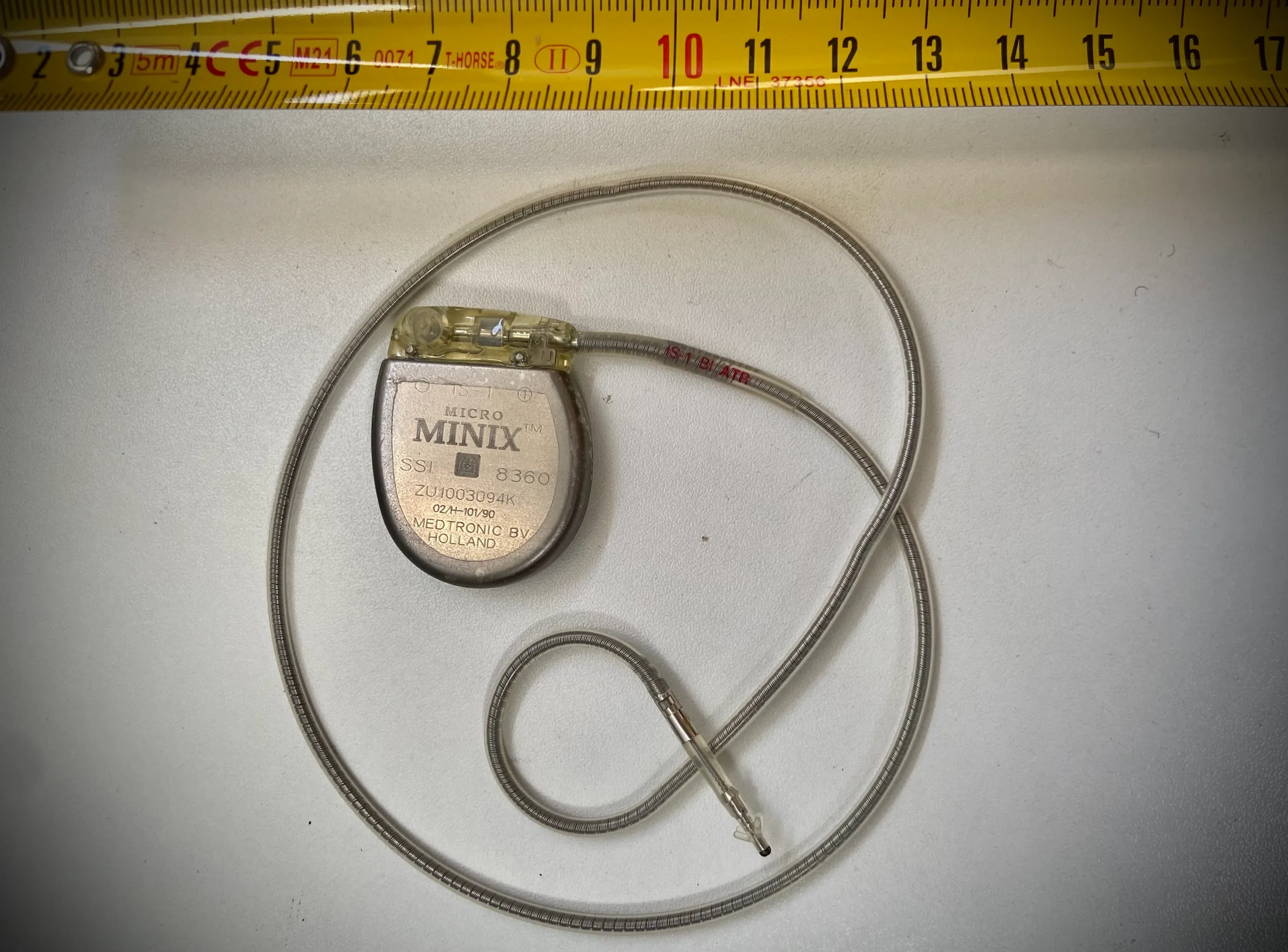
Explanted Medtronic Micro Minix pacemaker with pacing electrode

Explanted Medtronic Micro Minix pacemaker with pacing electrode. An explanted Medtronic Micro Minix: the laser-welded titanium can, engraved and sealed, its lead coiled around it — the housing as built.

Kuroczynski, CC BY-SA 4.0, via Wikimedia Commons
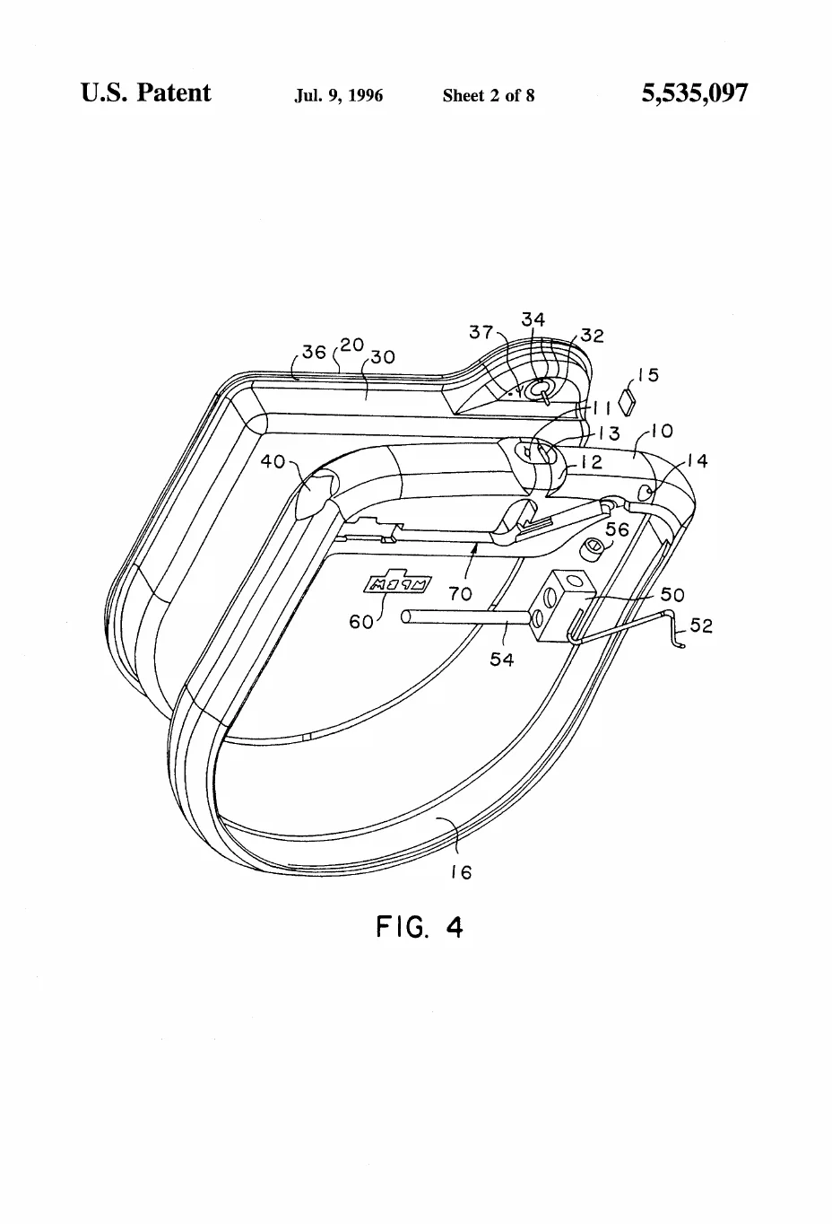
A perspective assembly view with the lid half pulled away from the main shell, exposing the connector hardware between them — the connector block, setscrew, spring contact, feedthrough pin, and sealing plug all floating in their positions like a freeze-frame of the device being put together.

US 5,535,097 · FIG. 4 — A perspective assembly view with the lid half pulled away from the main shell, exposing the connector hardware between them — the connector block, setscrew, spring contact, feedthrough pin, and sealing plug all floating in their positions like a freeze-frame of the device being put together.

United States patent drawing, public domain.

The claim and the can. Left, the sealed enclosure as it comes out of a chest; right, the 1993 drawing that taught its parts to locate themselves.

From the fire

The record in light

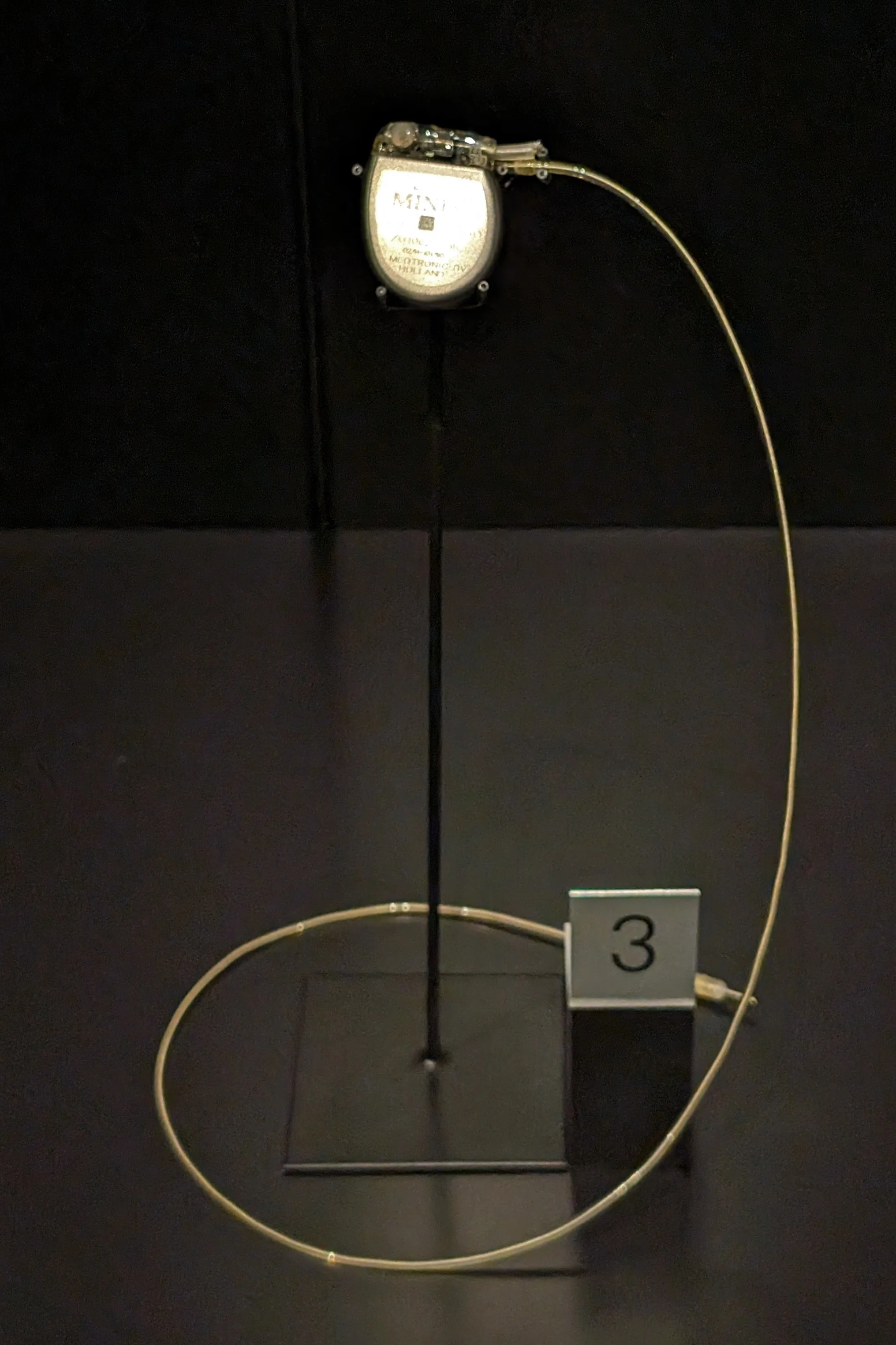
Medtronic Micro-Minix pacemaker (1993), Science Museum, London

Medtronic Micro-Minix pacemaker (1993), Science Museum, London. A 1993 Medtronic Micro-Minix in the Science Museum, London — a device from exactly the filing year of the first housing patent, presented as the artifact it became.

The wub, CC BY-SA 4.0, via Wikimedia Commons
From the file

Schematics of fire

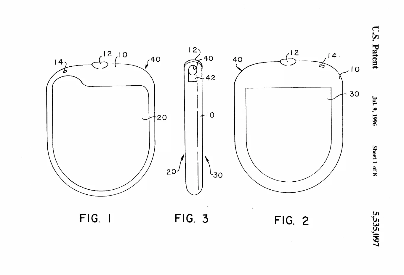
Three plain outline views of the finished pacemaker can — front, back, and razor-thin edge-on — establishing its rounded D shape, the connector bore at the top corner, and the feedthrough spot on the rim.

US 5,535,097 · FIGS. 1-3 — Three plain outline views of the finished pacemaker can — front, back, and razor-thin edge-on — establishing its rounded D shape, the connector bore at the top corner, and the feedthrough spot on the rim.

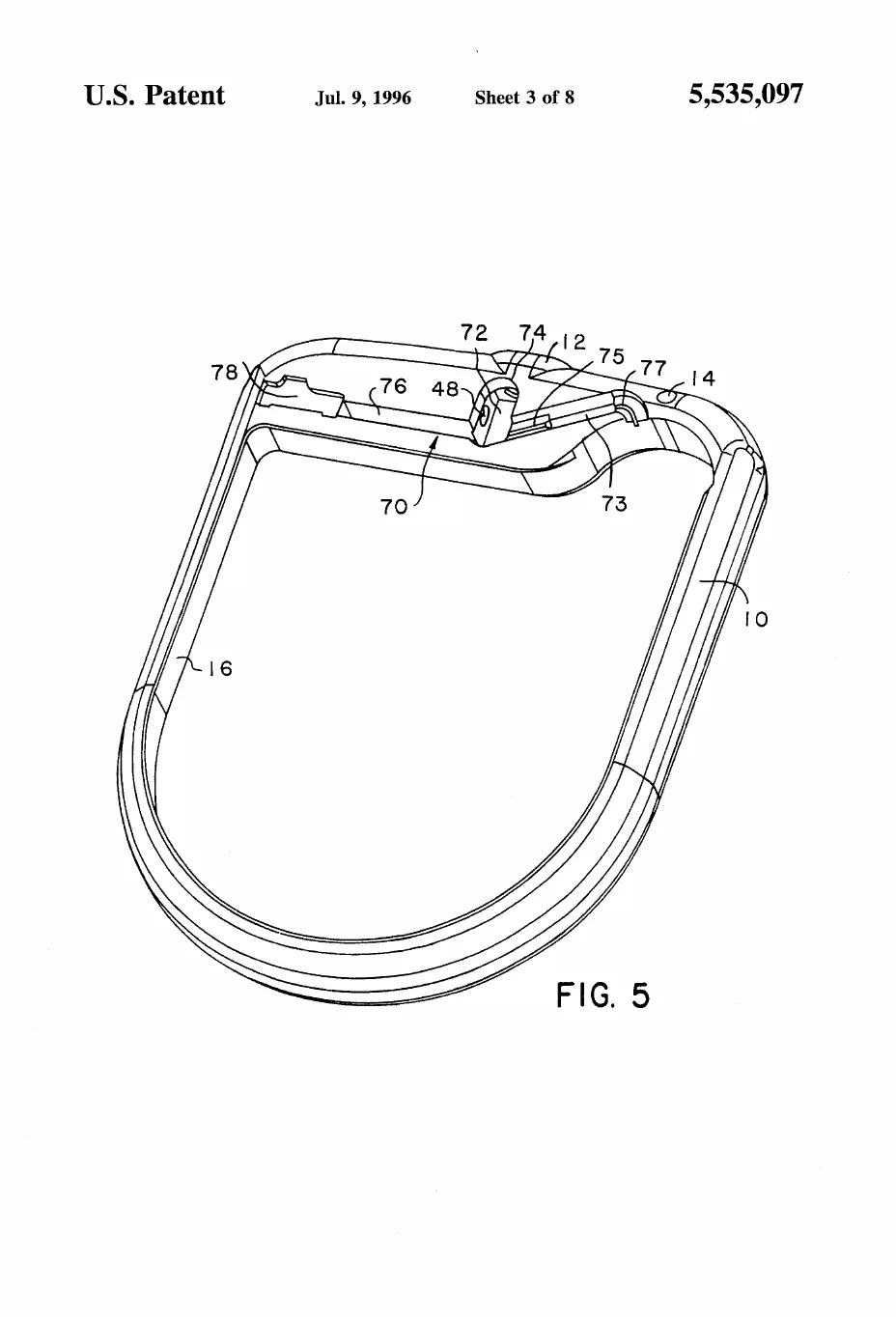
The open main shell viewed from above with the lid removed, showing the stepped interior ledge along the top edge where the feedthrough and connector parts seat themselves — the self-locating geometry at the heart of the claim.

US 5,535,097 · FIG. 5 — The open main shell viewed from above with the lid removed, showing the stepped interior ledge along the top edge where the feedthrough and connector parts seat themselves — the self-locating geometry at the heart of the claim.

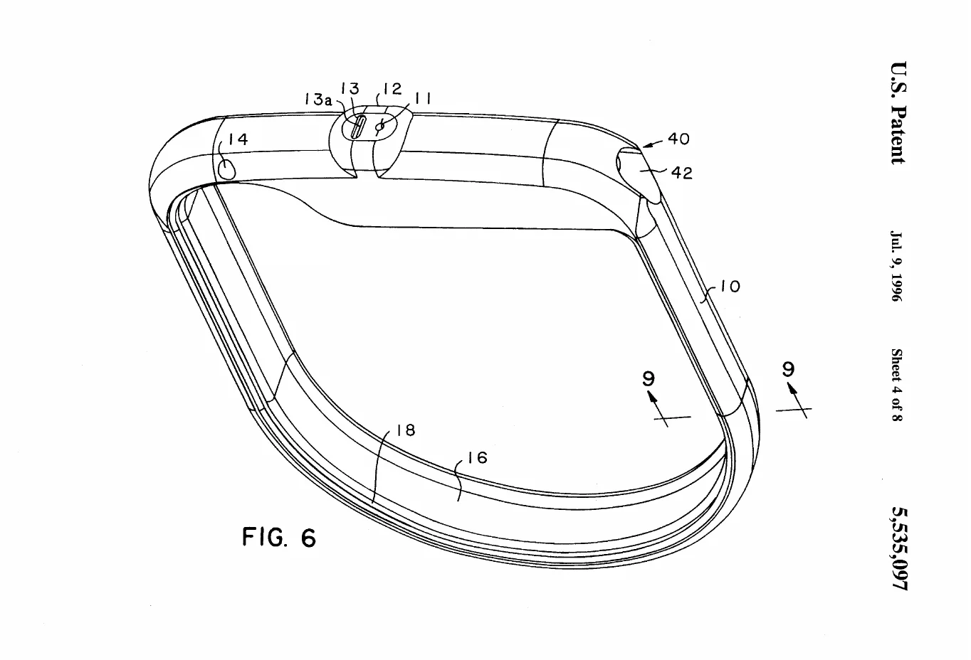
A perspective of the closed housing from the connector end, showing the molded shroud, the lead-receiving bore and its slotted aperture, and the section line for the later cross-section cuts.

US 5,535,097 · FIG. 6 — A perspective of the closed housing from the connector end, showing the molded shroud, the lead-receiving bore and its slotted aperture, and the section line for the later cross-section cuts.

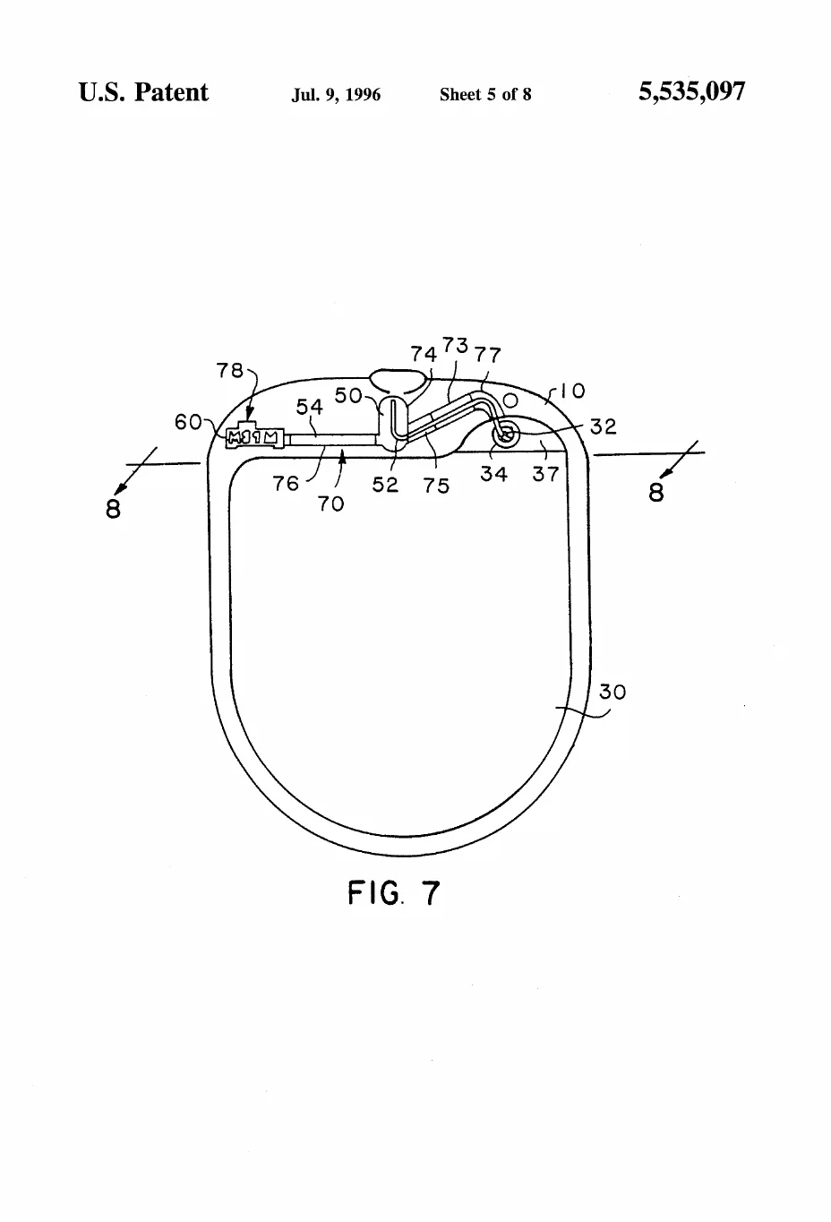
A flat side view of the can with hidden lines revealing the internal plumbing along the top edge — the wire path running from the feedthrough over to the connector block and setscrew — plus the big battery cavity filling the body.

US 5,535,097 · FIG. 7 — A flat side view of the can with hidden lines revealing the internal plumbing along the top edge — the wire path running from the feedthrough over to the connector block and setscrew — plus the big battery cavity filling the body.