The problemT1 · from the patentUS5885471A
A rate-responsive pacemaker needs to know when its patient is active so it can raise the heart rate to match. The sensor of choice was a piezoelectric cantilever beam — a tiny diving board that generates voltage as it flexes with body motion. The trouble, per US5885471's background: prior-art beams were so fragile that dropping the device from a few feet could snap them, and the solder/epoxy bonding methods of the day caused yield losses and inconsistent output. A sensor destined to be sealed inside a human chest for a decade cannot be that delicate.
The principleT1 · from the patentUS5885471A
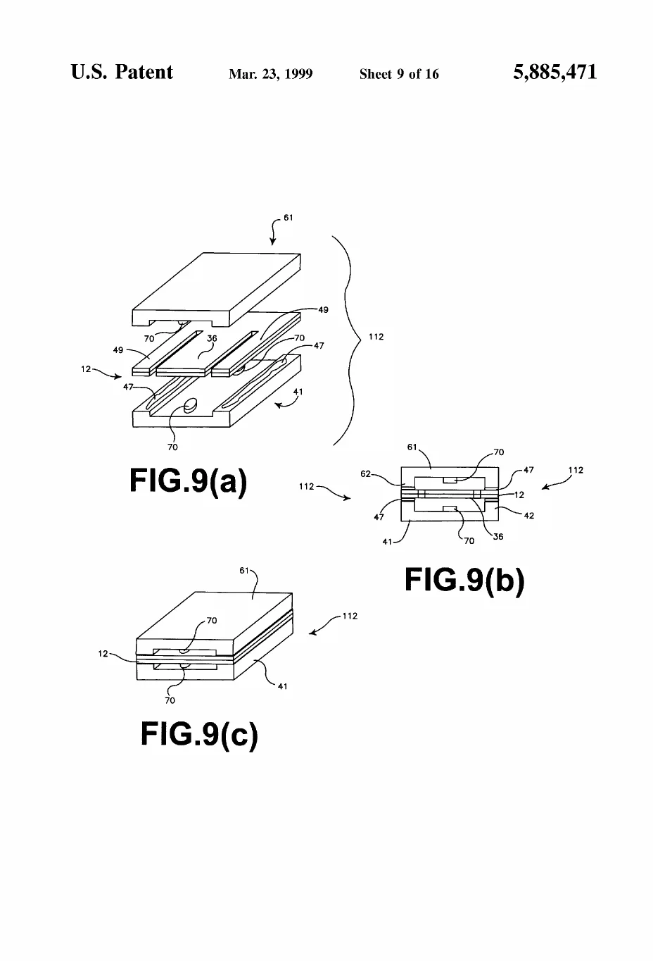
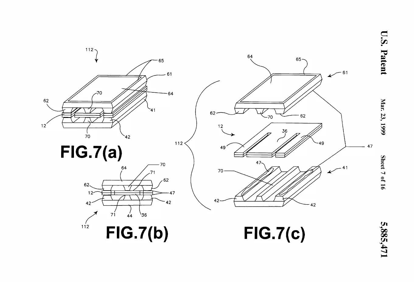
Piezoelectricity + mechanical over-travel protection. A piezoelectric sheet converts beam deflection (acceleration) directly into charge — no power needed to sense. The inventive step in US5885471 (D. Ruben, first-listed inventor) is claim 1's stop: a structure placed just above/below the beam's free end that lets it flex through its normal sensing range but arrests it before the deflection that would fracture it. Embodiments include a central rail stop (FIGS. 7a-c), foam-tape stops (FIGS. 11a-c), and damping gel (FIGS. 16a-c) — mechanical airbags for a sensor the size of a grain of rice.
Plain-English registerT3 · interpretationconfidence: high
Think of a diving board over a pool: flex is the signal. This invention adds a hand a half-inch under the board — invisible to a normal dive, but it catches the board before a cannonball snaps it.
The orientation problemT1 · from the patentUS6216537B1
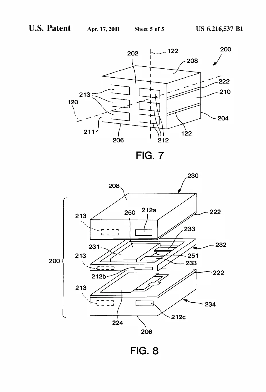
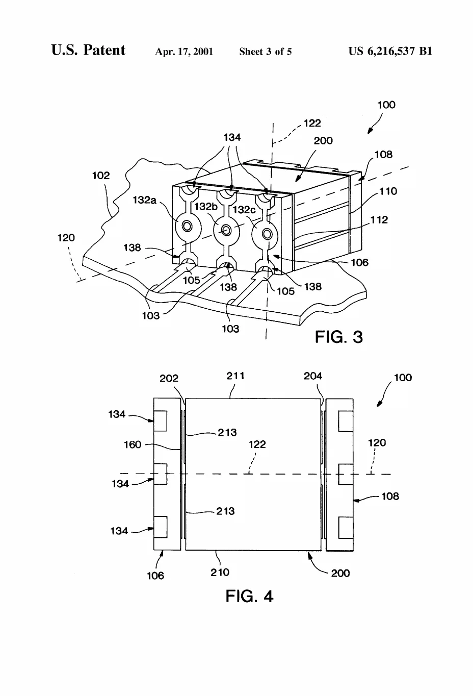
A second constraint: a beam accelerometer senses along one axis, and the clinically useful axis points into/out of the patient's chest — but the sensor mounts flat on a circuit board, which naturally aligns its sensitivity parallel to the board. US6216537's answer is a surface-mount package with multilayer conductive end caps that let the sensing element stand so its sensitivity axis is perpendicular to the board (claim 1), while remaining mass-producible and testable after assembly — sensor physics reconciled with electronics manufacturing.
Verified real-world contextT2 · external source
- The field's movement from piezoelectric activity sensing to accelerometer- based sensing — with faster, more proportional rate response — is documented in the engineering literature (comparative analysis, Srivastava et al., Measurement: Sensors 2021; Eur Heart J Suppl, "Evolution of pacing for bradycardias: sensors", accessed 2026-07-22). (An earlier draft attributed specific product names — Activitrax™/Thera™ — and the MOST trial to these sources; adversarial QA found neither actually says so, and those claims were removed. Product-name history is a question for David directly.)
- Accelerometer-based rate response remains standard in modern Medtronic devices; the leadless Micra's rate response is accelerometer-driven (Micra Accelerometer Sensor Study, clinicaltrials.gov NCT02930980).
Inference: where his work sits in that storyT3 · interpretationconfidence: medium
These four patents (1997–2001) land exactly in Medtronic's piezo→accelerometer transition era and solve its two practical blockers — survivability (US5885471) and manufacturable orientation (US6216537). It is reasonable to say this work helped carry activity sensing from lab bench to production pacemakers of that generation. Not claimed: that these specific patents are practiced in any named current product — no public source confirms that, and we don't assert it.
Set-piece note (for Presentation)T3 · interpretation
The natural animation: a beam flexing gently with a walking figure's gait → device drops → beam whips toward fracture → the stop catches it. One motion sequence teaches problem, principle, and novelty in ~6 seconds.