The Forge · Heat III · Laser Materials Processing · 2000-2025

The Laser Craft: light as a precision tool

US 6,501,043US 6,717,100US 7,872,208US 9,171,721US 8,796,109US 10,124,559US 10,981,355US 12,454,117US 11,999,014US 11,548,092US 11,969,821

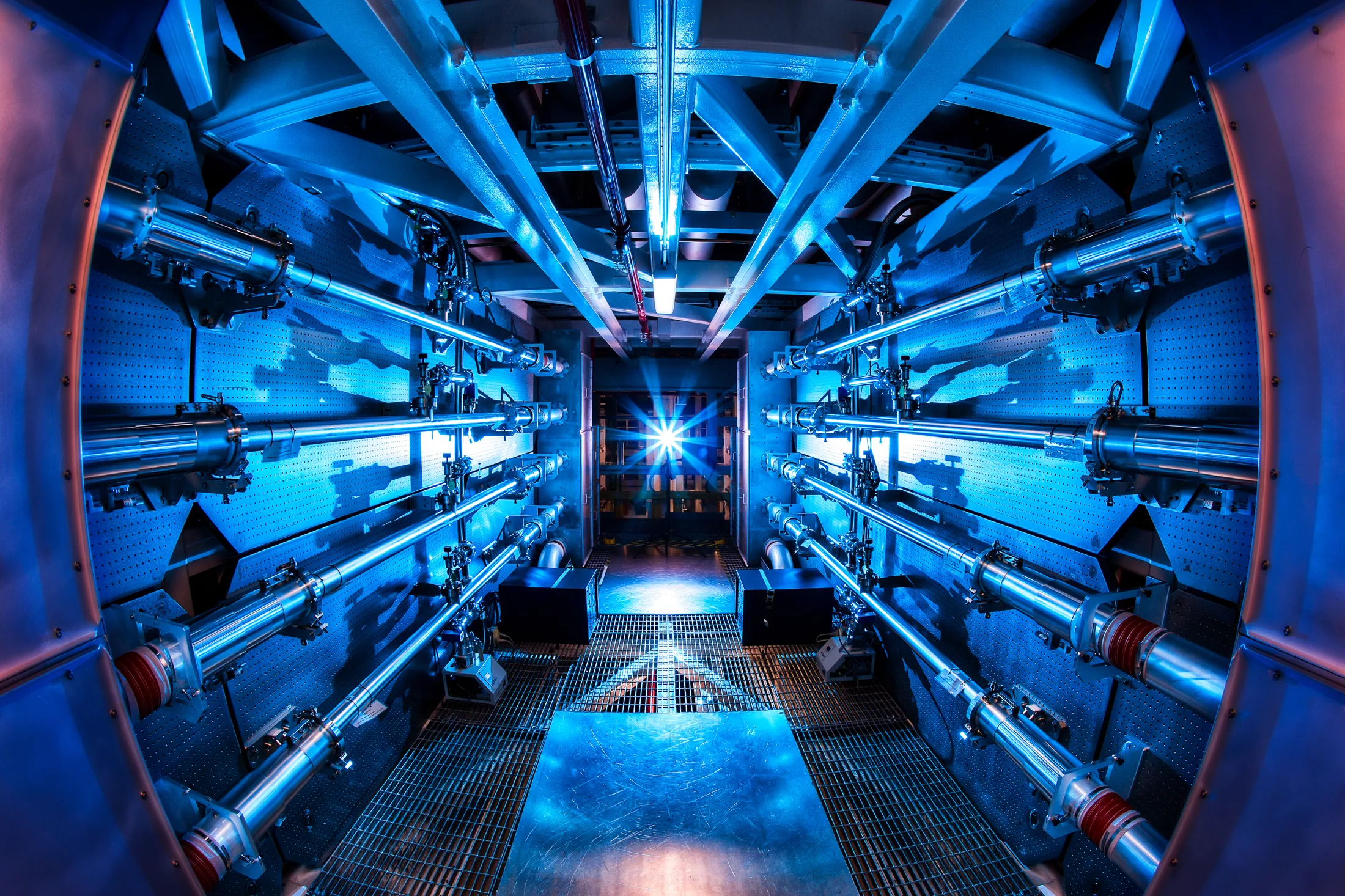
The preamplifier bay of the National Ignition Facility — the cathedral scale of the physics this chapter miniaturizes to a weld seam. — Photo: Lawrence Livermore National Laboratory, via Wikimedia Commons, CC BY-SA 3.0

The arcT3 · interpretationconfidence: high

Eleven grants over twenty-five years, all one discipline: using focused light to join, cut, and texture materials that conventional processes would damage. It begins with welding a ribbon and ends with atomic-scale bonds co-invented with Corning. This is the corpus's craft thread — the hands, where the feedthrough line is the cathedral those hands built.

Where it starts: the vibration problemT1 · from the patentUS6501043B1

Microelectronic connections were made by ultrasonic/thermosonic bonding — literally scrubbing parts together at high frequency. US6501043's background names the failure: vibration is "not well suited to bonding less rigid... structures," shakes parts out of position, and yields "weaker and inconsistent" bonds, while restricting usable metals. In a device where one bad joint is a surgery, that's intolerable.

The furnace — seconds heat wanders as √t · the whole part soaks everything gets hot The pulse — nanoseconds diffusion frozen at the interface · bond < 1000 nm the parts never really get hot
Set-piece · two ways to heat a joint

The physics of the whole chapter in one loop. Left: furnace time — over seconds, heat wanders as √t and the entire part soaks. Right: a nanosecond pulse — diffusion is frozen at the interface, and what remains is a bond thinner than a micron, cooling from white to ember. Static view: the soaked part beside the finished nano-bond.

The founding moveT1 · from the patentUS6501043B1

Sole inventor, claim 1: thread the ribbon under a bond head, then fire a laser through an aperture in the bond head itself, melting ribbon and pad into a single weld nugget — no vibration, no material restrictions, minimal tool wear; fiber-deliverable. The bond head holds; the light joins. Google Patents lists 35 citing patents.

Where it leadsT1 · from the patentUS10124559B2

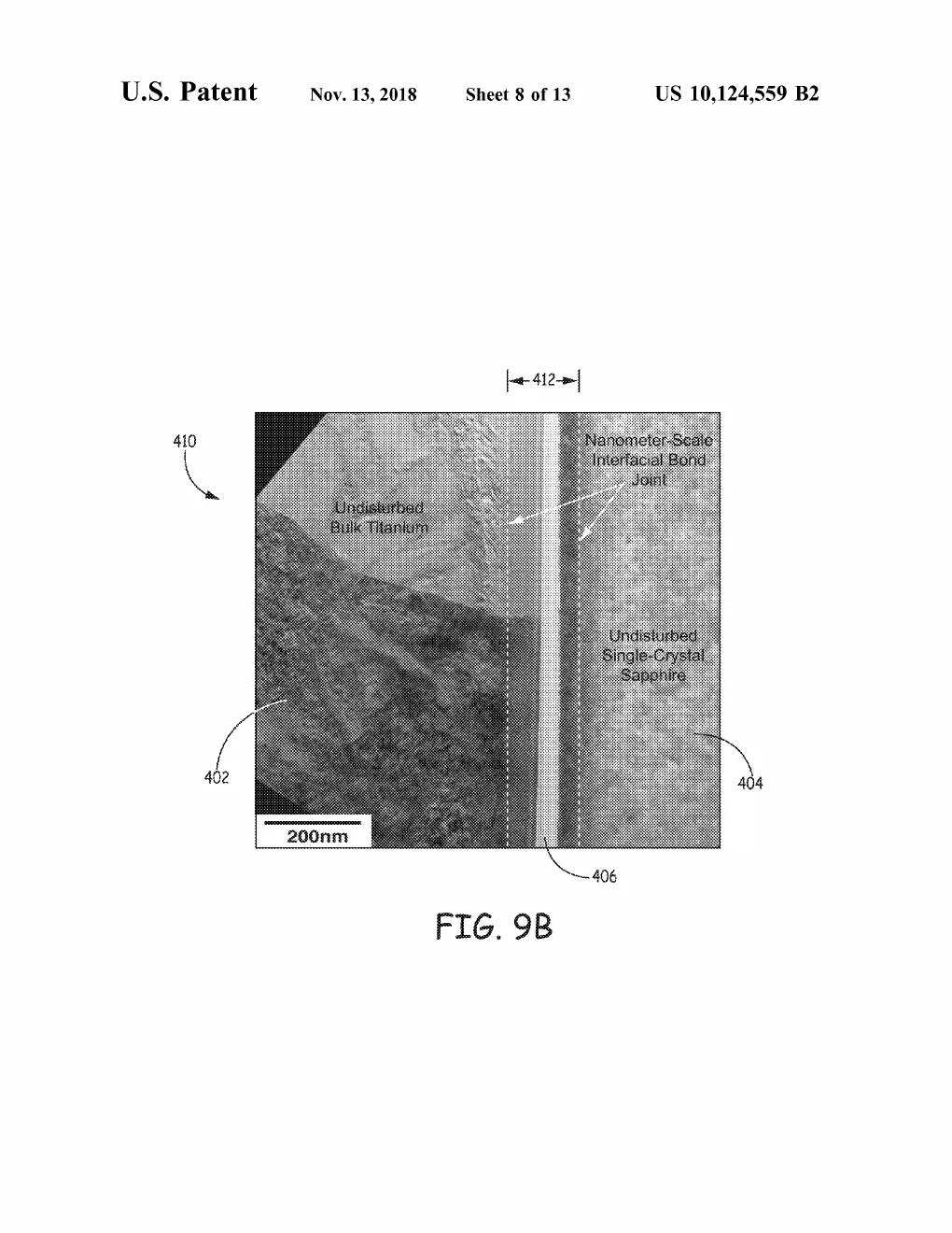
The endpoint (with Corning, US10124559 → US12454117): bond sapphire directly to titanium — transparent to opaque, insulator to metal — without the 600–1000 °C furnace such joints normally demand. The beam passes through the sapphire, deposits its energy at the interface, and forms a diffusion bond thinner than 1000 nanometers. "Kinetically limited" is the key idea: the pulse is too brief for heat to migrate, so diffusion happens only in that nano-zone — the parts never really get hot. Named applications reach past medical packaging to vacuum windows, photonics, even spacecraft. Alongside: laser-assisted direct bonding (US9171721), thin-film intermediate bonding (US8796109), two-beam laser cutting (US11999014), and underwater pulsed surface texturing (US11548092/US11969821).

Plain-English registerT3 · interpretationconfidence: high

Twenty-five years of the same magic trick at ever-smaller scale: get the heat exactly where the joint is and nowhere else. First a spot-weld through a tool's eye; finally, a bond a hundredth of a hair thick between a gem and a metal — made with a flash too fast for the heat to wander.

Cross-industry signalT2 · external source

The Corning co-assignment (US10124559, US10981355, US12454117 list both Medtronic, Inc. and Corning Incorporated as assignees — visible on the patents themselves) is the corpus's clearest external-validation marker: a materials-science giant putting its name beside his on the invention.
Drawing, meet reality

The claim beside the fire

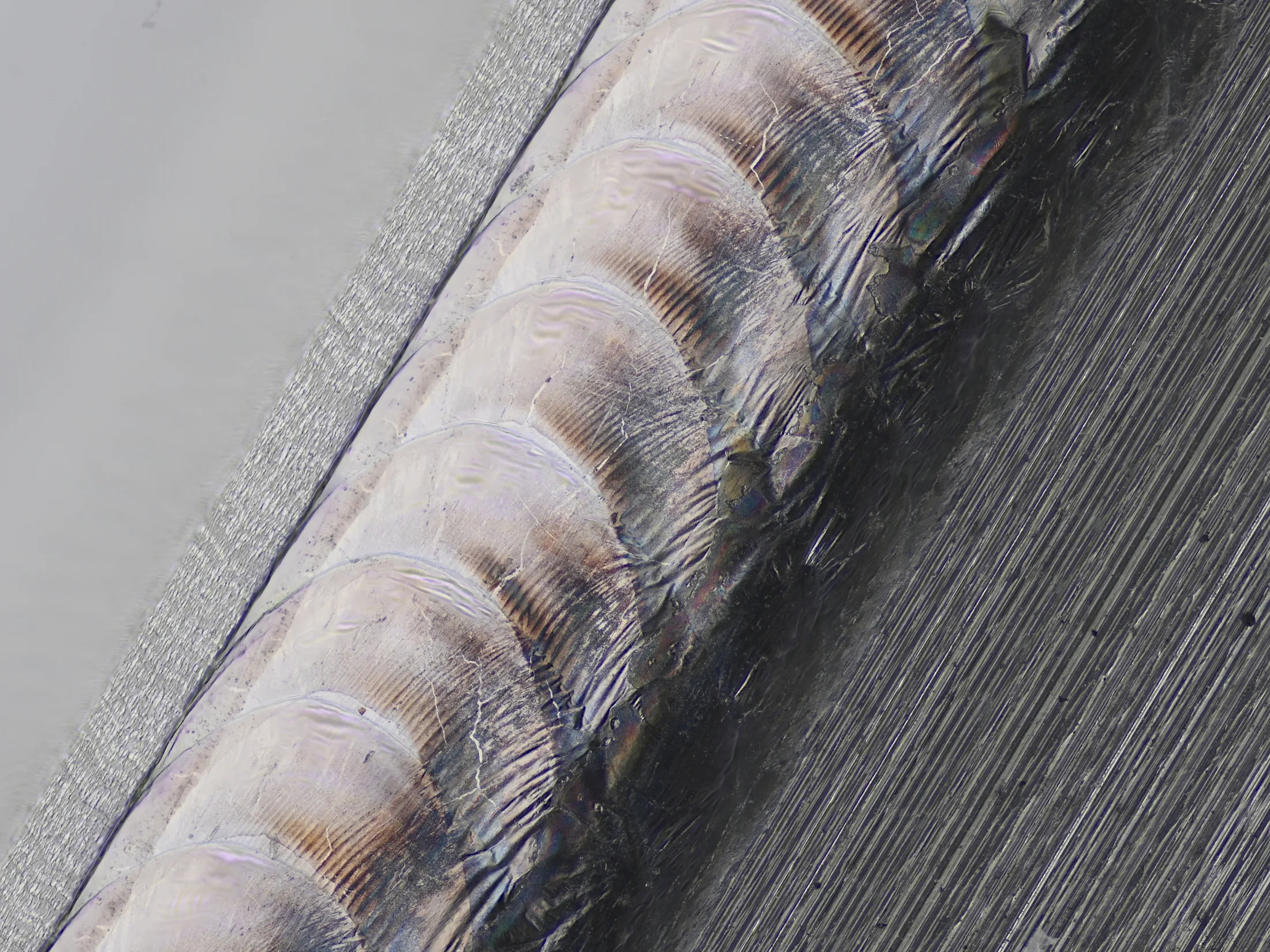
Macro of an overlapping pulsed laser weld seam hermetically sealing a helium-filled hard drive

Macro of an overlapping pulsed laser weld seam hermetically sealing a helium-filled hard drive. A focus-stacked macro of an overlapping pulsed laser weld seam, hermetically sealing a metal enclosure — the craft, executed.

Photo: Phiarc, via Wikimedia Commons, CC BY-SA 4.0
A labeled electron-microscope cross-section (200 nm scale bar) with plain-English callouts: undisturbed bulk titanium on the left, undisturbed single-crystal sapphire on the right, and the nanometer-scale interfacial bond joint measured between dashed lines in the middle.

US 10,124,559 · FIG. 9B — A labeled electron-microscope cross-section (200 nm scale bar) with plain-English callouts: undisturbed bulk titanium on the left, undisturbed single-crystal sapphire on the right, and the nanometer-scale interfacial bond joint measured between dashed lines in the middle.

United States patent drawing, public domain.

The seam and its cross-section: beside the photographed weld, the patent’s own electron-microscope plate of a kinetically-limited bond — sapphire fused to titanium across less than 1000 nanometers.

From the fire

The record in light

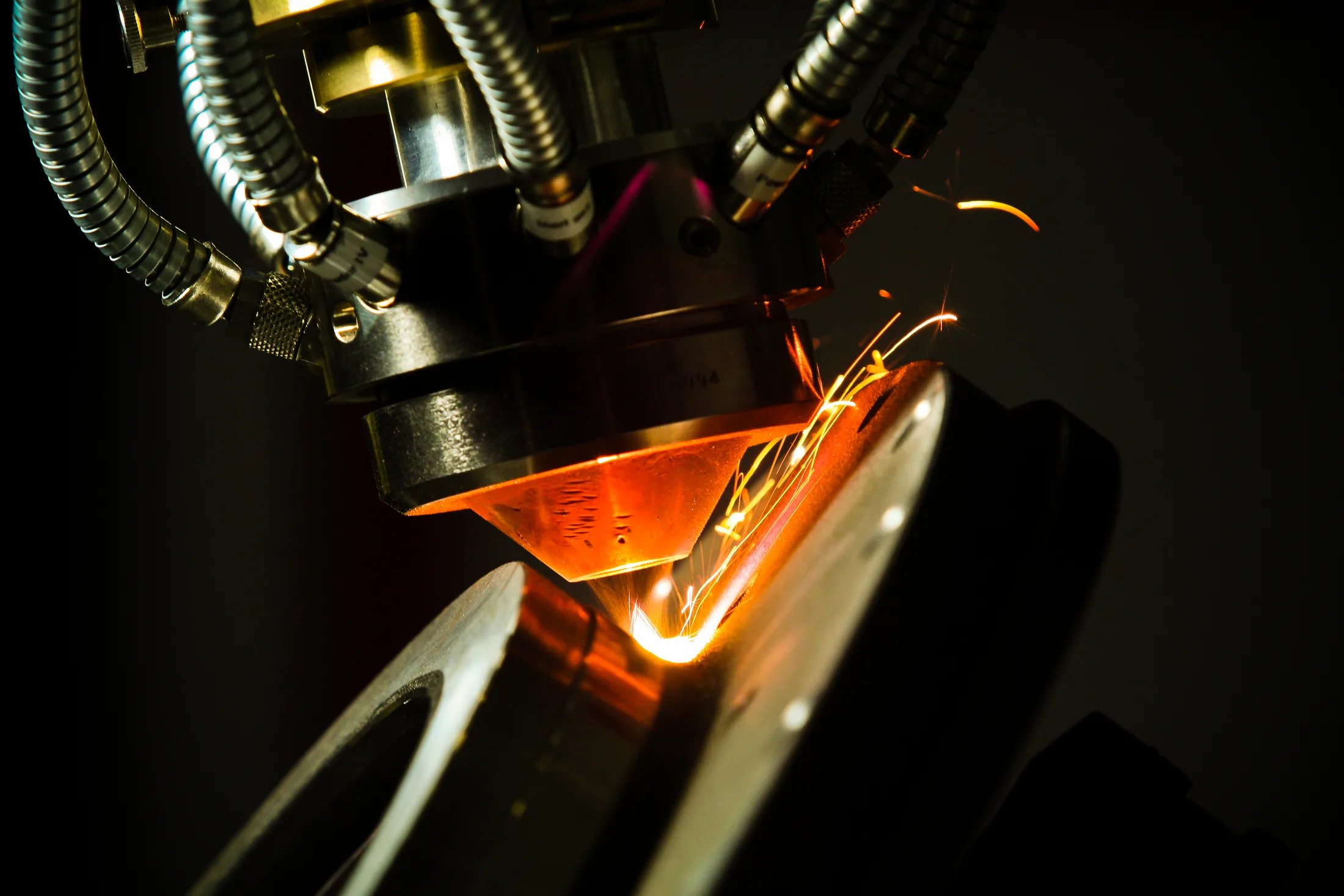
Laser cladding head with glowing melt pool and sparks (Laserové navařování 2)

Laser cladding head with glowing melt pool and sparks (Laserové navařování 2). A laser deposition head firing into metal: melt pool, sparks, black air. Industrial cousin of the pulses that seal implants.

Photo: LaserTherm, via Wikimedia Commons, CC BY-SA 4.0
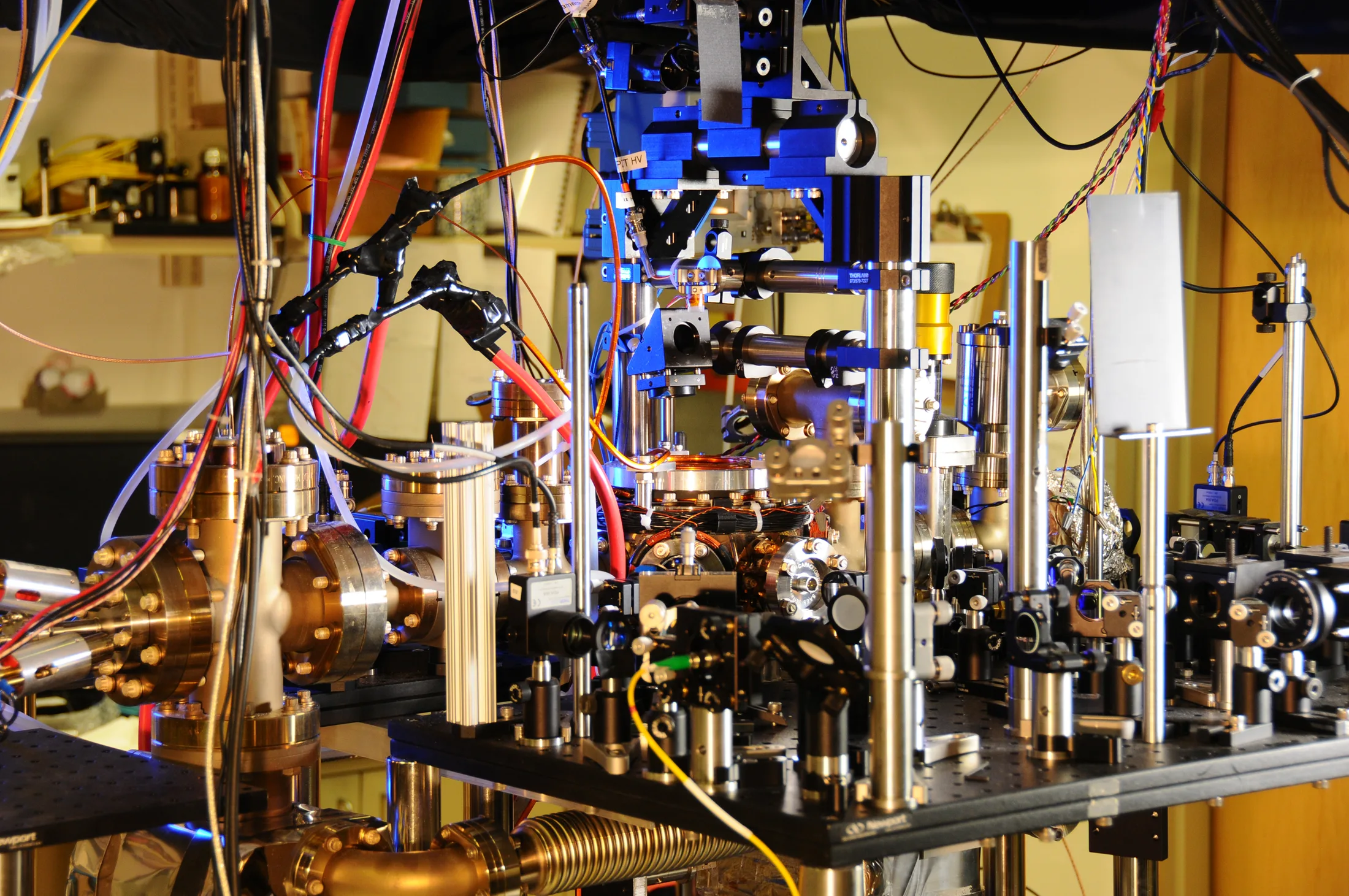
NIST ytterbium lattice atomic clock — laser table, fibers, and vacuum chamber

NIST ytterbium lattice atomic clock — laser table, fibers, and vacuum chamber. A working laser bench in honest clutter — fibers, mirrors, vacuum brass. Precision optics as a daily craft, not a diagram.

National Institute of Standards and Technology, public domain, via Wikimedia Commons
From the file

Schematics of fire

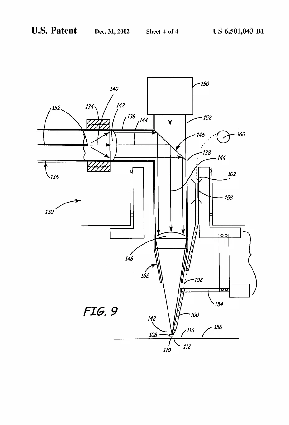
A full cross-sectional schematic of the welding apparatus, tracing the laser beam from its source through a turning mirror and focusing lens down a conical housing and out through the bond head's aperture onto the ribbon-and-pad joint.

US 6,501,043 · FIG. 9 — A full cross-sectional schematic of the welding apparatus, tracing the laser beam from its source through a turning mirror and focusing lens down a conical housing and out through the bond head's aperture onto the ribbon-and-pad joint.

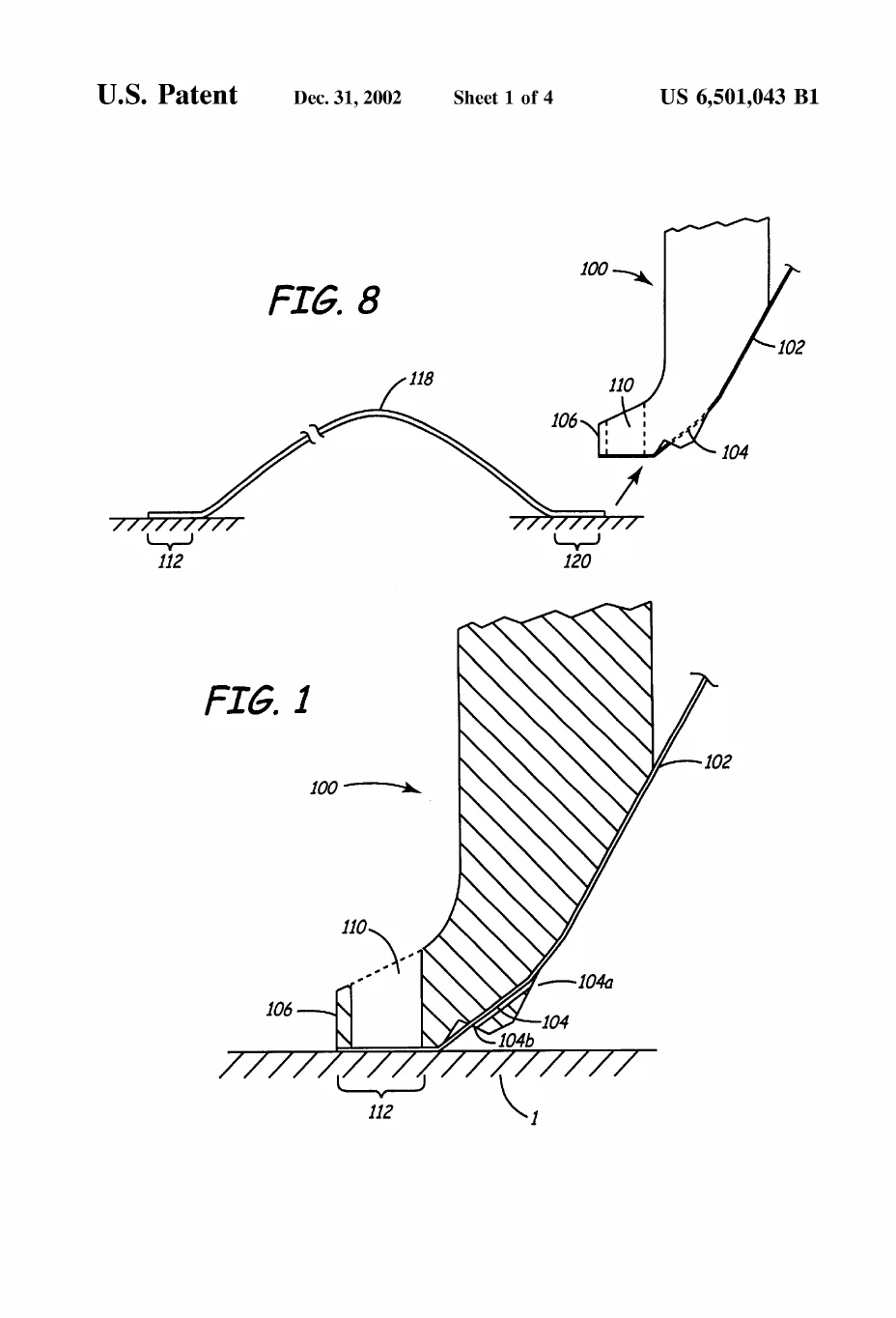
A cross-section of the bond-head foot pressing a metal ribbon onto its pad with the laser aperture and forming weld nugget visible beneath it, plus a view of the finished ribbon arching between its two bonded pads.

US 6,501,043 · FIG. 1, FIG. 8 — A cross-section of the bond-head foot pressing a metal ribbon onto its pad with the laser aperture and forming weld nugget visible beneath it, plus a view of the finished ribbon arching between its two bonded pads.

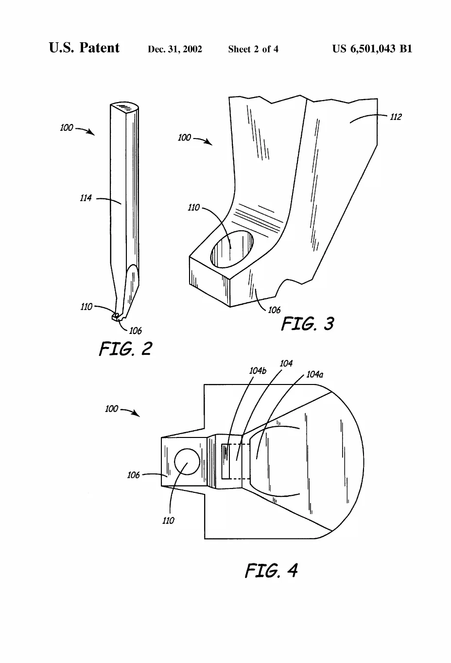
Perspective and magnified close-up views of the bonding tool itself, revealing the aperture bored straight through its foot — the eye the laser fires through — and the weld region seen through that opening.

US 6,501,043 · FIG. 2, FIG. 3, FIG. 4 — Perspective and magnified close-up views of the bonding tool itself, revealing the aperture bored straight through its foot — the eye the laser fires through — and the weld region seen through that opening.

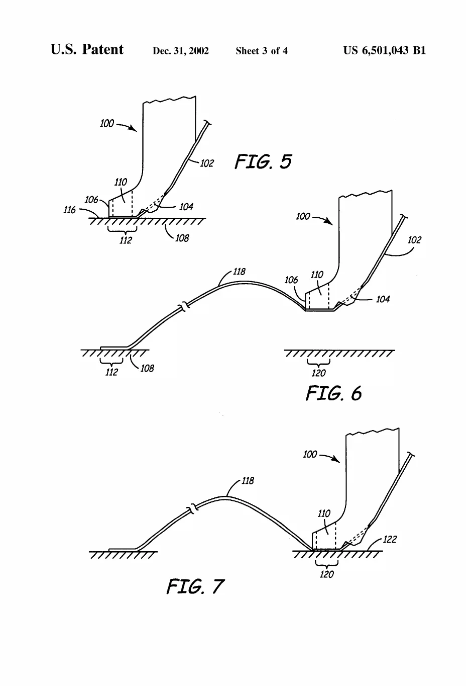
A three-step storyboard of the bonding sequence: the tool clamps and laser-welds the ribbon to a first pad, then the ribbon is looped over and welded to a second pad to complete the connection.

US 6,501,043 · FIG. 5, FIG. 6, FIG. 7 — A three-step storyboard of the bonding sequence: the tool clamps and laser-welds the ribbon to a first pad, then the ribbon is looped over and welded to a second pad to complete the connection.